
Ansi, Jis Globe Valve
Ansi, Jis Globe Valve Detail:
Product Description
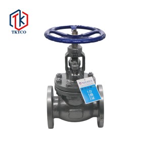
J41H flanged globe valves are designed and manufactured to API and ASME standards.Globe valve, also known as cut-off valve, belongs to the forced sealing valve, so when the valve is closed, pressure must be applied to the disc to force the sealing surface not to leak.When the medium from the lower part of the disc into the valve, the operation force needed to overcome the resistance is the friction force of the stem and packing and the thrust generated by the pressure of the medium, the force of the valve is larger than the force of the open valve, so the diameter of the stem should be large, otherwise the stem top bending fault will occur
Product Structure

Main Size And Weight
J41H(Y) Class 150/10K
|
Size |
inch |
1/2 |
3/4 |
1 |
1 1/4 |
1 1/2 |
2 |
2 1/2 |
3 |
4 |
5 |
6 |
8 |
10 |
12 |
14 |
16 |
|
mm |
15 |
20 |
25 |
32 |
40 |
50 |
65 |
80 |
100 |
125 |
150 |
200 |
250 |
300 |
350 |
400 |
|
|
L |
mm |
108 |
117 |
127 |
140 |
165 |
203 |
216 |
241 |
292 |
356 |
406 |
495 |
622 |
698 |
787 |
914 |
|
H |
mm |
163 |
193 |
250 |
250 |
291 |
350 |
362 |
385 |
490 |
455 |
537 |
707 |
788 |
820 |
||
|
W |
mm |
100 |
125 |
160 |
160 |
180 |
220 |
250 |
280 |
320 |
320 |
400 |
450 |
560 |
560 |
J41H(Y) Class 300/20K
|
Size |
inch |
1/2 |
3/4 |
1 |
1 1/4 |
1 1/2 |
2 |
2 1/2 |
3 |
4 |
5 |
6 |
8 |
10 |
12 |
|
mm |
15 |
20 |
25 |
32 |
40 |
50 |
65 |
80 |
100 |
125 |
150 |
200 |
250 |
300 |
|
|
L |
mm |
152 |
178 |
203 |
216 |
229 |
267 |
292 |
318 |
356 |
400 |
445 |
559 |
622 |
711 |
|
H |
mm |
163 |
193 |
250 |
250 |
291 |
345 |
377 |
405 |
468 |
620 |
*708 |
*777 |
*935 |
*906 |
|
W |
mm |
100 |
125 |
160 |
160 |
180 |
220 |
250 |
280 |
320 |
400 |
*450 |
*500 |
*560 |
*600 |
Product detail pictures:


Related Product Guide:
We have been ready to share our knowledge of internet marketing worldwide and recommend you suitable merchandise at most aggressive rates. So Profi Tools present you very best price of money and we are ready to develop alongside one another with Ansi, Jis Globe Valve , The product will supply to all over the world, such as: Detroit , Philadelphia , Wellington , Hard work to keep making progress, innovation in the industry, make every effort to first-class enterprise. We try our best to build the scientific management model, to learn abundant professional knowledge, to develop advanced production equipment and production process , to create the first-call quality products, reasonable price , high quality of service , quick delivery , to give you create new value .
Cooperate with you every time is very successful, very happy. Hope that we can have more cooperation!
Related products
-
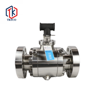
METAL SEAT (FORGED) BALL VALVE
Product Overview Forged steel flange type high pressure ball valve closing parts of the ball around the center line of the valve body for rotation to open and close a valve, the seal is embedded in the stainless steel valve seat, the metal valve seat is provided with a spring, when the sealing surface wear or burn, under the action of the spring to push the valve seat and the ball to form a metal seal.Exhibit unique automatic pressure release function, when the valve lumen medium pressure mor...
-
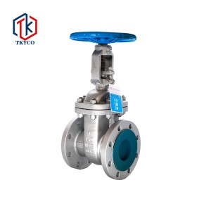
Ansi, Jis Gate Valve
Product Features Product design and manufacturing in line with foreign requirements, reliable sealing, excellent performance. ② The structure design is compact and reasonable, and the shape is beautiful. ③ Wedge-type flexible gate structure, large diameter set rolling bearings, easy opening and closing. (4) The valve body material variety is complete, the packing, gasket according to the actual working conditions or user requirements reasonable selection, can be applied to various pressure, t...
-
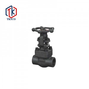
Forged Steel Gate Valve
Product Description Internal thread and socket welded forged steel gate valve fluid resistance is small, open and close the torque required is small, can be used in the medium to flow in two directions of the ring network pipeline, that is, the flow of media is not restricted.When fully open, the erosion of the sealing surface by the working medium is smaller than that of the globe valve.The structure is simple, the manufacturing process is good, and the length of the structure is short. Prod...


